Cut, then deform
Remove the reference-space sphere B₀, then map the remaining solid.
Φ(Ω₀ ∖ B₀)DeformSolid / Computational geometry
Model and edit solids after nonlinear deformation.FE-aligned boundaries made sampled geometry 105× more accurate at the finest tested resolution.
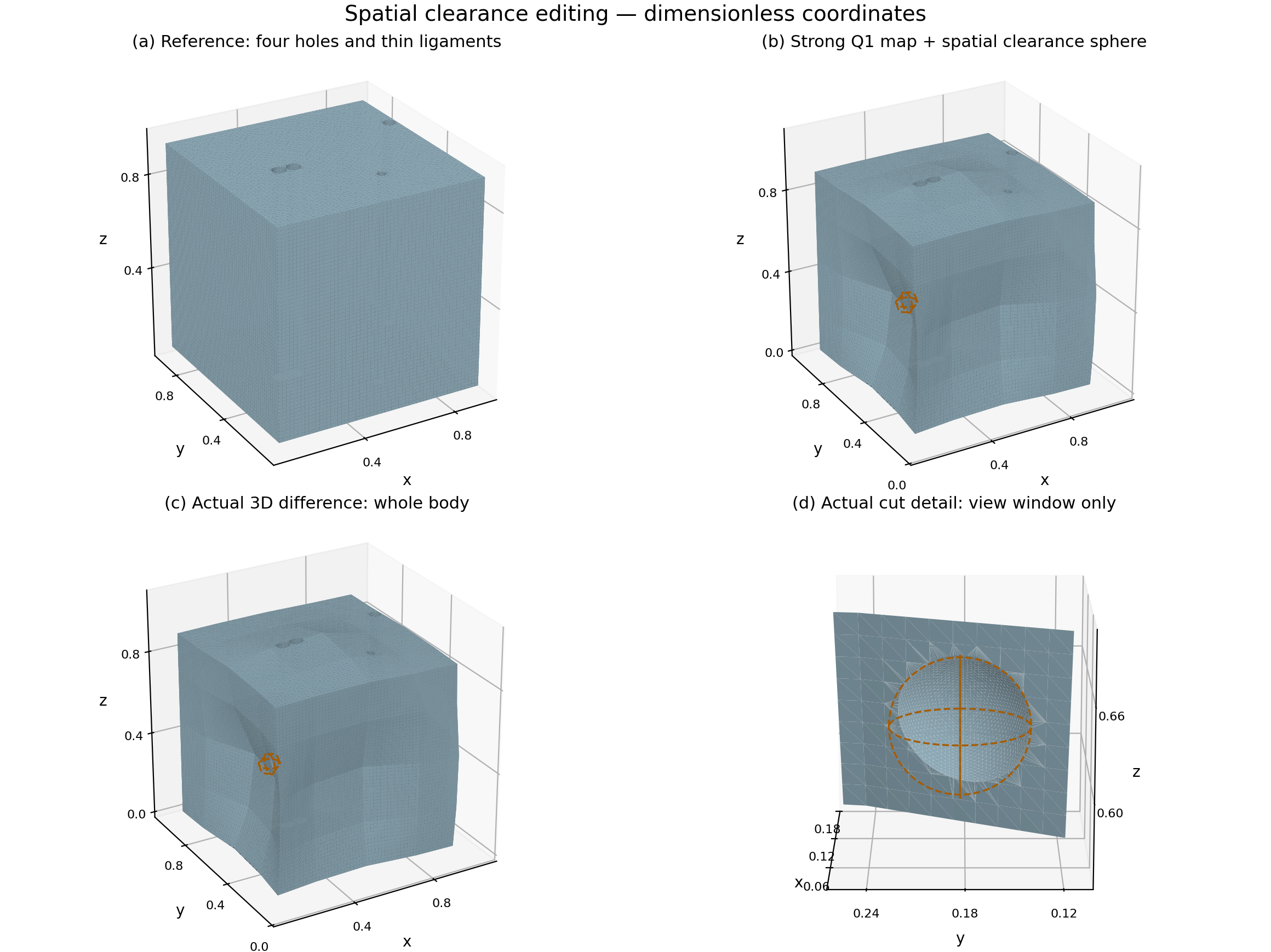
01 / Interactive geometry
Rotate the actual mesh, compare operations, and move inside the cut. These are the generated geometry outputs.
Rotate the meshes, reveal their interiors, and download double-precision OBJ geometry.
02 / Operations under deformation
Cutting in reference space and cutting in the deformed scene answer different geometric questions. Transporting the tool connects them.
Remove the reference-space sphere B₀, then map the remaining solid.
Φ(Ω₀ ∖ B₀)Subtract the independently specified spatial sphere B₁ from the deformed body.
Φ(Ω₀) ∖ B₁Map B₀ with the body, then execute a 3D Boolean in deformed space.
Φ(Ω₀) ∖ Φ(B₀)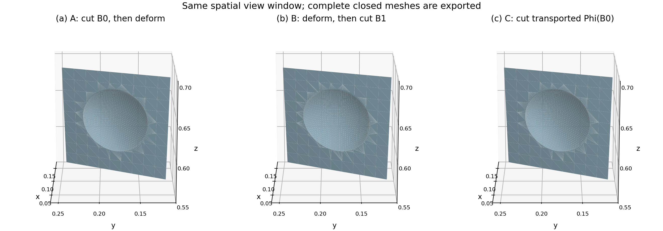
B₀: center (0.0525, 0.18, 0.62), radius 0.045. B₁: center (0.09942443490438002, 0.183131631211526, 0.6264289927536667), radius 0.045. The transported Φ(B₀) is generally not a sphere. Coordinates and volumes are dimensionless.
03 / Cross-section inspection
Compare closed contours at three fixed heights. Every displayed section has one material component and four holes.
Fine-mesh contours are shown in a shared coordinate frame. Independent inverse-field sections and local comparisons are in the section figure ↗.
04 / FE-aware accuracy
A deformed solid is reconstructed from a finite-element map. Its slope changes across element interfaces; edges crossing those interfaces can carry extra geometric error into the final Boolean output.
Smaller finest-level sampled geometric error with FE-aligned boundary reconstruction.
Observed convergence orders: without versus with FE alignment.
Input triangle count at the finest resolution.
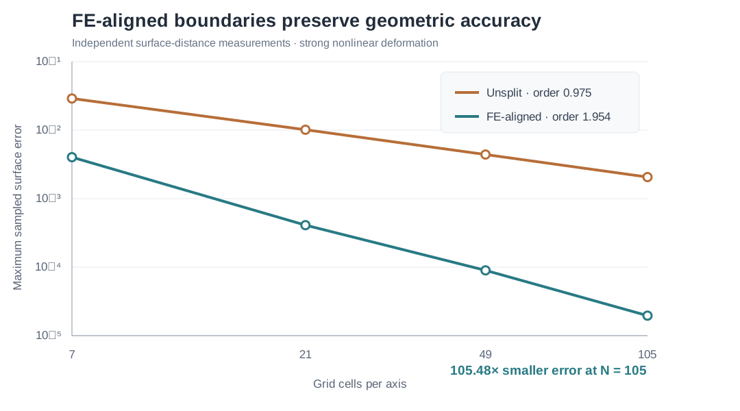
At the finest resolution, sampled maximum error decreased from 2.066 × 10⁻³ to 1.958 × 10⁻⁵. Four follow-up 3D Boolean outputs passed mesh checks and kept the expected four-hole sections. A separate standalone matched-input splitter exposed seam gaps near 10⁻¹³; the supported result is for the complete FE-aligned construction.
05 / High-performance compute
A native C++ evaluator performs the Q1 map, damped Newton inversion, and analytic CSG field evaluation in double precision. No per-query Python calls.
Native CPU speedup
at 2048² cells
Dense query throughput
single-thread C++
Maximum field difference
against Python
Caller-owned buffers and a stable structure-of-arrays C ABI.
Q1 mapping → Newton inverse → analytic CSG → per-query status.
Contiguous arrays connect native batch evaluation to Python geometry workflows.
| Grid cells | C++ | Python | Ratio |
|---|---|---|---|
| 512² | 0.0531 s | 0.4091 s | 7.71× |
| 1024² | 0.2146 s | 1.5482 s | 7.21× |
| 2048² | 0.8514 s | 6.1203 s | 7.19× |
One warmup and five measured runs per method/grid, single-thread CPU. Native compute excludes allocation and interop; Python uses the existing chunked reference path. These are measured implementation ratios. Download timings ↓
06 / Geometric consistency
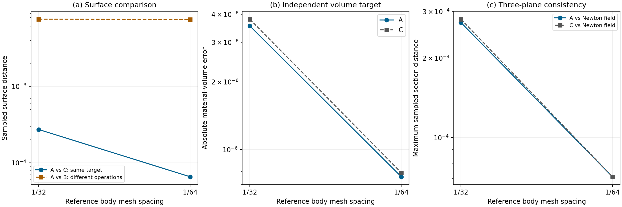
Mesh validity, closed contours, independent volume integration, and refinement connect the 3D result to its implicit definition.
Retained in all six comparison solids and all eighteen inspected mesh sections.
Fine A/C sampled surface distance for the transported-tool equivalence.
Fine transported-tool result's absolute volume error against independent Q1 integration.
Independent implicit-field checks covered twelve saved 3D Boolean meshes (49,636 point–mesh comparisons). All 4,214 definite label differences were within 1.892 × 10⁻⁴ of the mesh surface; 120 representative independent checks passed. They are sampled geometric differences near approximated boundaries, not exact label identity. Exp09 validation summary ↓
Build / Explore / Extend
The current release brings together the modeling application, the native C++ numerical engine, inspectable meshes, and measured results.